1/31/2016

Arduino Display w/GT20L16J1Y Japanese font ROM

GT20L16J1Y Japanese font ROM --- VFD

Copyright:vfd-fun     http://vfd-fun.blogspot.jp/

About
This trial is to display Japanese/Chinese characters on the VFD module with using Arduino and external font chip.

The interface of this font chip  GT20L16J1Y is using SPI.

Font ROM Info
Schematic
Character scroll display /Sample Program for Arduino
Refer - Font chip at
http://trac.switch-science.com/wiki/KanjiROM

VFD Module Program: 16x16 dot font scroll display on VFD Module
for Arduino and GU280X16G-7xxx
kanjiROM_test_gu280x16.txt


Wiring: Arduino, Font Chip ,Display Module(GU280X16G)
Arduino+Jpn Font + GU-7000 VFD


Font ROM to Display Bitmap Conv.

1/15/2016

Retro VFD Clock with Lacquerware Stand

Single digit VFD Tubes 1970s' controlled by ATMEGA MCU.

This lacquerware(Japanese Urushi) Stand is 1920-1930 made.

Noritake VFD(Ise Electronics Corp. )"Itron" , This model, only a couple hundreds of tubes remain.

Next step would be fixing the design of PCB and lacquerware stand,making this retro 4digit clocks.
Unfortunately, this will be the very last 200 units batch available globally.

1/13/2016

Glass TouchKeypad and IchigoJam part2

A Glass Touch Keypad and IchigoJam Trial 2

IchigoJam と ガラス タッチキーパッド I2C接続
 

Key pads are formed with Aluminum fine pattern
Lower resistance than ITO
Continuous work after Dec10 2015 post
 

This time, the glass touch keypad worked.

Touch controller : Atmel AT42QT2120
 
Set up - put a printed sheet underneath the glass keypad.


1. Wiring(5)

I2C connection to the IchigoJam
 SDA--->IN3
 SCL---->EX1
 
 /Change---IN1        (Watch status change) normally "H"

I2C Address  0x1C   (Fixed)
 
VCC--3.3V
GND--GND

2. Initialize of AT42QT2120(Atmel sensor driver chip)

Reset  "/Change "   L to H      (Normally H but L at turn-on)
First thing to do;
Reset the chip!   This was a bit tricky.
 
Send reset command   0x07,0xFF(any nonzero value)
wait 500msec. (250msec Min?)
Dummy status read from the chip (I did this but not shown in the spec)

3. Read Keydata

Check  any key detection status change "/Change"
  Wait /Change  H->L
or
  Read sensor detection status (0x02)
 
Read data command   0x03
   data  D7,D6,----D0
Read data command  0x04
   data  x,x,x,x,D11,D10,D9,D8
 
Note;
I saw no key data even when "/Change" became L.
I just ignored null data.
 

4. Convert data to Key number

The order of  leadout from the glass keypad is not
the same as sensor chip input/output numbering.
I had to convert the sensor data by the following
order.
 
Glass keypad 1,2, 3, 4, 5,6, 7,8,9,10,11,12
sensor data    1,0,11,10,2,4,7,9,3, 5, 6, 8

Multi-touch can be read.
 

 5. Other settings

This Atmel chip can be set in various sensing mode.
For the pratical use it might be needed.

6. Trial kit

This kit is not  being sold, but free samples are available both in the US and Japan(Tech Support)
I'll provide some samples for the educational /leaarning purposes.


7. Atmel AT42QT2120


AT42QT2120 PCB for Glass touch keypad
Comm Mode : 1 to 12 keys, 1-9 wheel or slider
Standalone Mode:1 to 5 keys
 

Reference of pin numbers and Key number

1/01/2016

I2C Test: TouchKey Display and IchigoJam

I2C Test :TouchKey Display Module and IchigoJam

IchigoJam とGU-D ModuleをI2Cで接続してみた

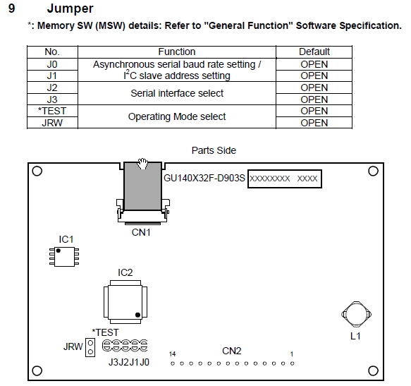
GU140X32F-D903S

140x32 dot matrix VFD with 8x2  Capacitive touch keypad 

1. IchigoJam a BASIC computor for kids

What is  the "IchigoJam";
LPC1114 based MCU board includes, Basic interpreter on chip, NTSC video output, PS2 Keyboard input,Digital/Analog I/O, UART,I2C..
 
Note:IchigoJam Basic uses "# "showing hex data "h"

2. I2C Connection to the IchigoJam

SDA: IN3
SCL:  EXT
 
Connection: GU-D Module
SDA:  PIN2
SCL:   PIN5
I2C Addr   50h (can be selected)

3. IchigoJam BASIC command

1) Write message data thru I2C
POKE #700,........         Store Module command
POKE #703,.........        Store message data ASCII

An example for IchigoJam BASIC command for I2C write
I2CW(#50,#700,3,#703,7)
Send the data 3bytes from Addr 700h as a command and send 7bytes from 703h as message data.
 
2) Read Key data
POKE #710,#1f,#48,#10........   Store Module command to read data
 
I2CR(#50,#710,3,#720,4)    :  
Send the command (#10) for "All Touch SW Status Read" , 3bytes from 710h.
Save read 4bytes data to 720h---723h.
 
3) Result
Read data form the module  in #720,#721,#722,#723
 
#720 : Function Id (#10)       (Just confirm the sent command data)
#721 : Data Length (2)         (Tell how many bytes sent)
#722 : Keydata  (SW16-9)
#723:  Keydata  (SW8-1)
 

4. Display functions of Module :GU140X32F-D903S

1) How to indicate your  message on the module screen :Refer the spec for detail

Just send ASCII data or Bitmap to  the module ,no need to use libraries to display simple text and bitmap.
 
Display control commands
Bitmap memory
international character fonts incl Asian fonts
Macro programming


Connection
GU140X32F-D903F
 
Result: Data read from Module
 
IchigoJam Monitor with GU140X32F-D903S


-Reference-

Display GU140X32F-D903S information