ラベル IchigoJam の投稿を表示しています。 すべての投稿を表示

5/07/2016

IchigoJam Choco Vendor 2 チロルチョコベンダー続

IchigoJam Choco Vendor + Card Reader

 
Gave up to make a coin accepter then used a card reader instead.
 
Just sense the card insertion and it enables the button switch.
 
コインアクセプタをつくるのは、たいへんなので、カード挿入式にした。
といっても、挿入確認だけ。
 
カードを入れると、一回だけチロルチョコボタンが押せる。
 
・タミヤのギヤー は、最低速にしたので、トルクが強い。チロルが詰まると固まる。
モーターはOFFにしても惰性で動く。


5/03/2016

IchigoJam Choco Vendor チロルチョコベンダー

Made this

Proto 0.1
Tested:  Circular motion to liner sliding  motion to push the choco out.
              SW the Tamiya Motor by a tr with OUTPUT of IchigoJam.
              Controlled by the IchigoJam(LPC1114)  and BASIC programming


タミヤのギヤーボックスを使用。モーターをトランジスタで制御。

BASIC programming

Wait the start  tact switch ON
Start motor
Timer(TICK) reset for "timeout"
Wait the limit switch ON
Stop the motor after WAIT for the  point
Monitor the HALT swith to avoid the overload bcause of  jamming choco

Next project

Coin acceptor


2/05/2016

Traffic Signal Programming Kit for Kids


Traffic Signal Light Programming Kit for Kids

Kid's computer "Ichigojam" BASIC Programming 

Purpose

Open the first step for age 9-12 kids to learn programming.
Encourage kids to learn fundamental programming knowledge with lighting LEDs as a traffic light.
Use fundamental commands to control LEDs.
 
 
9yr old kids understood the following commands and program flow;
OUT
WAIT
GOTO
--------------------

Wiring

IchigoJam board and LEDs
OUT1   LED (Green) via a resister to set the current.
OUT2  LED (Yellow) via a resister to set the current.
OUT3  LED (Red) via resister to set the current.
Each resister should be adjusted to set the LED current.
Normally 5 to 10mAea.

Programming Commands

Some hints

Stage 1:

Kids understand how OUT commands work
 
10 OUT1,1           'Light Green ON
20 WAIT 600       'wait approx 10sec.
30 OUT1,0           'Light Green OFF

Stage 2 :

Kids understand how INPUT command works

Change the signal light duration / timing
Input the each LED time from keyboard
 
10 INPUT"GREEN",G
20 INPUT"YELLOW",Y
30 INPUT"RED",R
 
WAIT G*60 

Stage 3

Kids can use to simpify the program flow
FOR NEXT
IF THEN ELSE


 Reference

 
CU20027-Y1A Spec data (PDF)
UART interface, Just wire  TX to SI
Send ASCII character code to indicate.
 
Display Module/CU20027-Y1A  shows the light duration
 
 
Traffic Signal Light fixture by 3D printer


1/13/2016

Glass TouchKeypad and IchigoJam part2

A Glass Touch Keypad and IchigoJam Trial 2

IchigoJam と ガラス タッチキーパッド I2C接続
 

Key pads are formed with Aluminum fine pattern
Lower resistance than ITO
Continuous work after Dec10 2015 post
 

This time, the glass touch keypad worked.

Touch controller : Atmel AT42QT2120
 
Set up - put a printed sheet underneath the glass keypad.


1. Wiring(5)

I2C connection to the IchigoJam
 SDA--->IN3
 SCL---->EX1
 
 /Change---IN1        (Watch status change) normally "H"

I2C Address  0x1C   (Fixed)
 
VCC--3.3V
GND--GND

2. Initialize of AT42QT2120(Atmel sensor driver chip)

Reset  "/Change "   L to H      (Normally H but L at turn-on)
First thing to do;
Reset the chip!   This was a bit tricky.
 
Send reset command   0x07,0xFF(any nonzero value)
wait 500msec. (250msec Min?)
Dummy status read from the chip (I did this but not shown in the spec)

3. Read Keydata

Check  any key detection status change "/Change"
  Wait /Change  H->L
or
  Read sensor detection status (0x02)
 
Read data command   0x03
   data  D7,D6,----D0
Read data command  0x04
   data  x,x,x,x,D11,D10,D9,D8
 
Note;
I saw no key data even when "/Change" became L.
I just ignored null data.
 

4. Convert data to Key number

The order of  leadout from the glass keypad is not
the same as sensor chip input/output numbering.
I had to convert the sensor data by the following
order.
 
Glass keypad 1,2, 3, 4, 5,6, 7,8,9,10,11,12
sensor data    1,0,11,10,2,4,7,9,3, 5, 6, 8

Multi-touch can be read.
 

 5. Other settings

This Atmel chip can be set in various sensing mode.
For the pratical use it might be needed.

6. Trial kit

This kit is not  being sold, but free samples are available both in the US and Japan(Tech Support)
I'll provide some samples for the educational /leaarning purposes.


7. Atmel AT42QT2120


AT42QT2120 PCB for Glass touch keypad
Comm Mode : 1 to 12 keys, 1-9 wheel or slider
Standalone Mode:1 to 5 keys
 

Reference of pin numbers and Key number

1/01/2016

I2C Test: TouchKey Display and IchigoJam

I2C Test :TouchKey Display Module and IchigoJam

IchigoJam とGU-D ModuleをI2Cで接続してみた

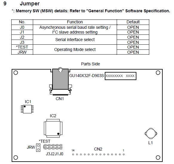
GU140X32F-D903S

140x32 dot matrix VFD with 8x2  Capacitive touch keypad 

1. IchigoJam a BASIC computor for kids

What is  the "IchigoJam";
LPC1114 based MCU board includes, Basic interpreter on chip, NTSC video output, PS2 Keyboard input,Digital/Analog I/O, UART,I2C..
 
Note:IchigoJam Basic uses "# "showing hex data "h"

2. I2C Connection to the IchigoJam

SDA: IN3
SCL:  EXT
 
Connection: GU-D Module
SDA:  PIN2
SCL:   PIN5
I2C Addr   50h (can be selected)

3. IchigoJam BASIC command

1) Write message data thru I2C
POKE #700,........         Store Module command
POKE #703,.........        Store message data ASCII

An example for IchigoJam BASIC command for I2C write
I2CW(#50,#700,3,#703,7)
Send the data 3bytes from Addr 700h as a command and send 7bytes from 703h as message data.
 
2) Read Key data
POKE #710,#1f,#48,#10........   Store Module command to read data
 
I2CR(#50,#710,3,#720,4)    :  
Send the command (#10) for "All Touch SW Status Read" , 3bytes from 710h.
Save read 4bytes data to 720h---723h.
 
3) Result
Read data form the module  in #720,#721,#722,#723
 
#720 : Function Id (#10)       (Just confirm the sent command data)
#721 : Data Length (2)         (Tell how many bytes sent)
#722 : Keydata  (SW16-9)
#723:  Keydata  (SW8-1)
 

4. Display functions of Module :GU140X32F-D903S

1) How to indicate your  message on the module screen :Refer the spec for detail

Just send ASCII data or Bitmap to  the module ,no need to use libraries to display simple text and bitmap.
 
Display control commands
Bitmap memory
international character fonts incl Asian fonts
Macro programming


Connection
GU140X32F-D903F
 
Result: Data read from Module
 
IchigoJam Monitor with GU140X32F-D903S


-Reference-

Display GU140X32F-D903S information


12/21/2015

IchigoJam BASIC command I2C WRITE

IchigoJam BASIC command I2C WRITE


The IchigoJam (Kids computer) Basic is capable to handle I2C interfacce.

Send data must be stored in the memory area.
Use Poke to store the data to be sent.
Use Peek to read the received data.

https://github.com/fu-sen/IchigoJam-BASIC/blob/master/I2CW.txt

I2CW
0.9.9~
-----------------------------------------------------------
[ 機能 ]
メモリに入れている値を
I2C シリアルバスで接続されたデバイスへ送ります
[ コマンド 書式 ]
<返し値>=I2CW(<I2C アドレス>,<コマンド開始番地>,<コマンド長さ>,<書込メモリ開始番地>,<書込メモリ長さ>)
[ 例 ]
R=I2CW(`1010000,#700,2,#702,16)
[ 解説 ]
<I2C アドレス> は I2C 経由で情報を送るデバイスです。
I2C デバイスには A0~A2 端子の接続に応じて
固有のスレープアドレスを持ちます。これを指定します。
値は 0~127(`0000 000 ~ `1111 111)です。
これに READ/WRITE ビットの WRITE を付加し送信します。
READ/WRITE ビットを含めない値になる事にご注意下さい。
その後 <コマンド開始番地> から <コマンド長さ> にあるコマンド、
<書込メモリ開始番地> から <書込メモリ長さ> にある
データを送信します。
<コマンド開始番地> <書込メモリ開始番地> は
IchigoJam から渡す値を入れたメモリの場所です。
<コマンド長さ> <書込メモリ長さ> はバイト単位で長さを示します。
POKE で予め値を入れておいた後に I2CW でデータを送信します。

1.0.0 beta11 で Esc キーを押す事で送受の中断を行えるようになりました。


IchigoJam command Serial Output

IchigoJam BASIC

https://github.com/fu-sen/IchigoJam-BASIC
UART Serial interface

How to ommunicate with other devices from Ichigojam board.

IchigoJam has UART Serial Output. TXD and  RXD Input
Use "PRINT" command to send data.

Note:

command "PRINT"


LOCATE で縦位置を -1 にしている場合は(例えば LOCATE 0,-1)
画面出力を行わず、シリアル出力のみ行います。
0.9.4 より対応しています。


PRINT
-----------------------------------------------------------
[ 機能 ]
画面へ表示します。シリアルへ出力します。
[ コマンド 書式 ]
PRINT "<文字列>"[;]
PRINT <数>[;]
? "<文字列>"[;]
? <数>[;]
[ 例 ]
PRINT "HI!"
[ 解説 ]
文字列の場合は " で囲みます。
末尾に ; (セミコロン)を付けると、連結する事が可能です。
; を付けない場合は改行を含めます。一番下の行では1行上にスクロールします。
PRINT の代わりに ? を使用する事が可能です。
シリアル接続を行っている場合は、そのまま出力されます。
LOCATE で縦位置を -1 にしている場合は(例えば LOCATE 0,-1)
画面出力を行わず、シリアル出力のみ行います。
0.9.4 より対応しています。

IchigoJam command I2C interface-data read

Memo  IchigoJam BASIC "I2C command"


https://github.com/fu-sen/IchigoJam-BASIC

I2CR
0.9.9~
-----------------------------------------------------------
[ 機能 ]
I2C シリアルバスで接続されたデバイスからデータを取り出し、メモリに格納します。
 
 
[ コマンド 書式 ]
<返し値>=I2CR(<I2C アドレス>,<コマンド開始番地>,<コマンド長さ>,<読込メモリ開始番地>,<読込メモリ長さ>)
[ 例 ]
R=I2CR(`1010000,#700,2,#702,16)
[ 解説 ]
<I2C アドレス> は I2C 経由で情報を得るデバイスです。
I2C デバイスには A0~A2 端子の接続に応じて
固有のスレープアドレスを持ちます。これを指定します。
値は 0~127(`0000 000 ~ `1111 111)です。
これに READ/WRITE ビットの READ を付加し送信した後、
デバイスからの受信を得ます。
READ/WRITE ビットを含めない値になる事にご注意下さい。
次に <コマンド開始番地> から <コマンド長さ> にある
コマンドを実行します。
コマンドは POKE で予め用意して下さい。
その後 I2C から得たデータを <読込メモリ開始番地> から
<読込メモリ長さ> で収納します。
格納した情報は PEEK で実際の値を取得して下さい。
<コマンド開始番地> <読込メモリ開始番地> は
IchigoJam のメモリの場所です。
<コマンド長さ> <読込メモリ長さ> は
バイト単位で長さを示します。
1.0.0 beta11 で Esc キーを押す事で
受診の中断を行えるようになりました。

12/11/2015

IchigoJam で VFD Moduleに日本語(JP language)を表示してみる

日本語表示

IchigoJam+VFD MODULE(蛍光表示管) 

VFD MODULE GU256X64C-3900

 
VFD MODULE 蛍光表示管モジュールは、日本製でキャッシュレジスタなどに使われているものです。液晶とは異なり、自発光で、見やすい表示です。
 
簡体字:、繁体字、韓国字のフォントを標準搭載しているモデルを使いました。
 
各国の文字コードを入力すれば、表示できます。
UNICODEではありません。
日本字 JP: JISX208 シフトJIS
簡体字 CN:GB2312-80
繁体字 TW:Big5
Korea  :
 
文字の大きさや、コードの種類、いろいろな制御は、コマンドを送って行います。

接続は、パラレル8bitもありますが、簡単な文字表示だけですので、非同期シリアル UARTで、19200BPSを使いました。 IchigoJamは、19200BPSで安定してます。
文字表示だけなら、VFD Moduleのバッファがあふれることはなさそうで、Busy信号を見なくても大丈夫でした。(TXDで送りっぱなし)

ただし、このModuleは、RS232に準拠した入力レベルでしたので、IchigoJamの3.3V系に合うよう簡単なlevel変換をおこないました。

データは、IchigoJamからコードを送るだけですので、TXDとGNDの2本を接続しました。

VFD MODULEは、5V電源ですので、1A以上の容量のUSB電源から供給しました。
(コネクタ変換は必要です。USB電源の性能によっては、表示が立ち上がらないこともあります。
また、通信の初期値は、38400BPSになっていますので、基板のジャンパで、19200BPSに設定。

発光を見やすくするため、Green系のアクリル板を表示前面に貼りました。
お好みに応じて、青や、グレイでもいいですね。


VFD MODULEを動かすコマンドは、次回。